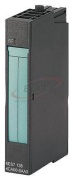
| Supply voltage |
| Load voltage L+ |
| ● Rated value (DC) |
24 V; From power module |
| Input current |
| from load voltage L+ (without load), max. |
30 mA |
| from backplane bus 3.3 V DC, max. |
10 mA |
| Power loss |
| Power loss, typ. |
0.6 W |
| Address area |
| Address space per module |
| ● Address space per module, max. |
4 byte |
| Analog inputs |
| Number of analog inputs |
2 |
| permissible input current for current input (destruction limit), max. |
40 mA |
| Cycle time (all channels) max. |
Number of active channels per module x basic conversion time |
| Input ranges |
| ● Voltage |
No |
| ● Current |
Yes |
| ● Thermocouple |
No |
| ● Resistance thermometer |
No |
| ● Resistance |
No |
| Input ranges (rated values), currents |
| ● -20 mA to +20 mA |
Yes; 50 Ohm |
| ● 4 mA to 20 mA |
Yes; 50 Ohm |
| Cable length |
| ● shielded, max. |
200 m |
| Analog value generation for the inputs |
| Measurement principle |
integrating |
| Integration and conversion time/resolution per channel |
| ● Resolution with overrange (bit including sign), max. |
14 bit; ±20 mA: 14 bits, 4 to 20 mA: 13 bits |
| ● Integration time (ms) |
16,7 / 20 ms |
| ● Interference voltage suppression for interference frequency f1 in Hz |
50 / 60 Hz |
| ● Conversion time (per channel) |
65 ms; 55 / 65 ms |
| Smoothing of measured values |
| ● parameterizable |
Yes; In four stages by means of digital filtering |
| ● Step: None |
Yes; 1 x cycle time |
| ● Step: low |
Yes; 4 x cycle time |
| ● Step: Medium |
Yes; 32 x cycle time |
| ● Step: High |
Yes; 64 x cycle time |
| Encoder |
| Connection of signal encoders |
| ● for current measurement as 2-wire transducer |
|
| — Burden of 2-wire transmitter, max. |
750 Ω |
| Errors/accuracies |
| Linearity error (relative to input range), (+/-) |
0.01 % |
| Temperature error (relative to input range), (+/-) |
0.005 %/K |
| Crosstalk between the inputs, min. |
-50 dB |
| Repeat accuracy in steady state at 25 °C (relative to input range), (+/-) |
0.05 % |
| Operational error limit in overall temperature range |
| ● Current, relative to input range, (+/-) |
0.6 % |
| Basic error limit (operational limit at 25 °C) |
| ● Current, relative to input range, (+/-) |
0.4 % |
| Interference voltage suppression for f = n x (f1 +/- 1 %), f1 = interference frequency |
| ● Series mode interference (peak value of interference < rated value of input range), min. |
70 dB |
| Isochronous mode |
| Isochronous operation (application synchronized up to terminal) |
No |
| Interrupts/diagnostics/status information |
| Diagnostic messages |
| ● Wire-break |
Yes; Measuring range 4 to 20 mA only |
| ● Group error |
Yes |
| ● Overflow/underflow |
Yes |
| Diagnostics indication LED |
| ● Group error SF (red) |
Yes |
| Parameter |
| Remark |
4 byte |
| Diagnostics wire break |
Disable / enable (only in measuring range 4 to 20 mA) |
| Measurement type/range |
deactivated / ±20 mA / 4 to 20 mA |
| Group diagnostics |
Disable / enable |
| Overflow/underflow |
Disable / enable |
| Potential separation |
| Potential separation analog inputs |
| ● between the channels |
No |
| ● between the channels and backplane bus |
Yes |
| ● Between the channels and load voltage L+ |
No |
| Isolation |
| Isolation tested with |
500 V DC |
| Dimensions |
| Width |
15 mm |
| Height |
81 mm |
| Depth |
52 mm |
| Weights |
| Weight |
40 g |
| last modified: |
11/21/2017 |